
 by
by This detailed guide outlines a nobgp configuration to assign a dedicated static public IP to each Server VLAN using Network Address Translation (NAT). This setup is particularly effective for multi-server environments where the goal is to group services or servers under a unique, reliable public IP address. Crucially, it is engineered to ensure that standard client traffic (non-server data) continues to use the native Internet connection, guaranteeing low latency for general browsing and desktop usage.
- Optimized Latency: The Main Network traffic continues to flow over the native Internet connection, ensuring the lowest possible latency for standard usage.
- Dedicated IP Assignment: A unique nobgp static public IP is assigned to each Server VLAN/LAN, allowing specific services to be grouped and addressed publicly.
- Centralized Management: Main network clients maintain full access to all server networks for seamless administration and maintenance.
- Performance Routing: All standard packets are fast-tracked by the router, with only tunnel traffic incurring the necessary processing overhead.
- Practical NAT Examples: Includes concrete Destination NAT (Dst-NAT) rule examples (e.g., forwarding port 80) to illustrate how to easily implement port forwarding to each segmented VLAN.
- Target Environment: This configuration was developed and tested on a MikroTik hAP ac² running RouterOS 7.20.6. (The logic remains adaptable to other RouterOS devices.)
- Starting Point: The configuration assumes a “clean slate” environment; the default configuration must be erased prior to starting the setup.
- Enhanced Security: The guide incorporates a basic firewall with a crucial default drop policy to secure the router and enforce traffic control.
Bypass CGNAT & Dynamic IPs: NOBGP static Public IP is directly routed
Discover nobgp by servperso: Static public IPs and IP pools are routed directly to your network via a high-availability VPN tunnel.
Schema
Physical network
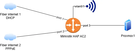
High-level design of implemented solution
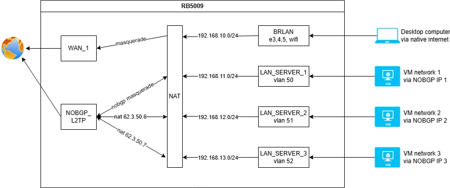
Resource used
For this configuration guide, we are using the following nobgp test resources as an example. It is essential that users replace these values with their own assigned static public IPs from their servperso nobgp account.
Additional Public IP Pool: 62.3.50.6/31 (This block contains the two extra static IPs that will be routed to the respective server VLANs.)
NOBGP Main Tunnel IP: 194.28.98.40 (This address will be assigned to the main VPN interface on the router.)
Initial router base configuration (Pre-NOBGP)
This section details the foundational network setup, including interfaces, local networks, and initial firewall rules, prior to integrating the nobgp VPN tunnel. We strongly recommend completing these steps first. A complete, combined configuration script (including all nobgp settings) will be provided at the end of this article for quick deployment.
/interface bridge
add name=BRLAN

/interface ethernet
set [ find default-name=ether1 ] name=WAN_1
set [ find default-name=ether2 ] name=WAN_2

/interface pppoe-client
add add-default-route=yes default-route-distance=31 disabled=no interface=WAN_2 name=WAN_2_PPPOE password=PPPOE_PASSWORD user=PPPOE_USER

/interface list
add comment="List public interfaces" name=WANS
add comment="List private interface" name=LANS

/interface wireless security-profiles
set [ find default=yes ] supplicant-identity=MikroTik
add authentication-types=wpa2-psk mode=dynamic-keys name=SERVPERSO_WIFI supplicant-identity="" wpa2-pre-shared-key=WIFI_PASSWORD

/interface wireless
set [ find default-name=wlan1 ] frequency=auto mode=ap-bridge security-profile=SERVPERSO_WIFI ssid=SERVPERSO_LABO wps-mode=disabled
set [ find default-name=wlan2 ] band=5ghz-n/ac channel-width=20/40mhz-Ce disabled=no frequency=auto mode=ap-bridge security-profile=SERVPERSO_WIFI ssid=SERVPERSO_LABO wps-mode=disabled

/ip pool
add name=POOL_LAN ranges=192.168.10.100-192.168.10.149

/ip dhcp-server
add address-pool=POOL_LAN interface=BRLAN lease-time=8h name=DHCP_LAN

/interface bridge port
add bridge=BRLAN interface=ether3
add bridge=BRLAN interface=wlan2
add bridge=BRLAN interface=wlan1
add bridge=BRLAN interface=ether4
add bridge=BRLAN interface=ether5

/interface list member
add interface=WAN_1 list=WANS
add interface=WAN_2_PPPOE list=WANS
add interface=WAN_2 list=WANS
add interface=BRLAN list=LANS

/ip address
add address=192.168.10.254/24 interface=BRLAN network=192.168.10.0

/ip dhcp-client
add default-route-distance=30 default-route-tables=main interface=WAN_1

/ip dhcp-server network
add address=192.168.10.0/24 dns-server=192.168.10.254 gateway=192.168.10.254

/ip dns
set allow-remote-requests=yes

/ip firewall address-list
add address=192.168.0.0/16 list=LAN_NETWORKS

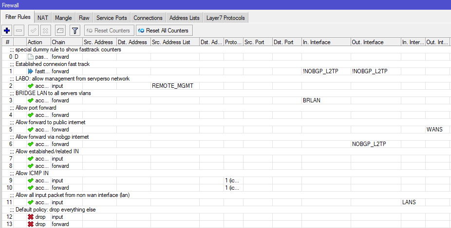
/ip firewall filter
add action=fasttrack-connection chain=forward comment="Established connexion fast track" connection-state=established,related hw-offload=yes
add action=accept chain=forward comment="Allow port forward" connection-nat-state=dstnat
add action=accept chain=forward comment="Allow forward to public internet" out-interface-list=WANS
add action=accept chain=input comment="Allow estabished/related IN" connection-state=established,related
add action=accept chain=forward connection-state=established,related
add action=accept chain=input comment="Allow ICMP IN" protocol=icmp
add action=accept chain=forward protocol=icmp
add action=accept chain=input comment="Allow all input packet from non wan interface (lan)" in-interface-list=LANS
add action=drop chain=input comment="Default policy: drop everything else"
add action=drop chain=forward

/ip firewall nat
add action=masquerade chain=srcnat comment="Source nat masquerade - Internet" out-interface-list=WANS
Configure nobgp on the router
Creating a dedicated routing table for nobgp 📌
This dedicated routing table is essential for ensuring that all outbound traffic originating from your nobgp public IPs is correctly forced back through the nobgp VPN tunnel.
This configuration is mandatory because most native Internet Service Providers (ISPs) employ anti-spoofing filtering (like uRPF checks). These filters would otherwise block any packet that carries a nobgp public source IP since it does not originate from the ISP’s assigned network.
/routing table
add disabled=no fib name=NOBGP
Add new interfaces and IP networks on the LAN side
In this step, we will create the necessary VLAN interfaces on the main bridge and assign them their corresponding private network ranges. These segmented networks are specifically designed to be mapped one-to-one with the NOBGP static public IP addresses in the subsequent steps.
Create VLAN
/interface VLAN
add interface=BRLAN name=LAN_SERVER_1 vlan-id=50
add interface=BRLAN name=LAN_SERVER_2 vlan-id=51
add interface=BRLAN name=LAN_SERVER_3 vlan-id=52
Add IP to VLAN
/ip address
add address=192.168.11.254/24 interface=LAN_SERVER_1 network=192.168.11.0
add address=192.168.12.254/24 interface=LAN_SERVER_2 network=192.168.12.0
add address=192.168.13.254/24 interface=LAN_SERVER_3 network=192.168.13.0
Adding the new LAN interfaces to the interface list
In our foundational setup, we utilize an interface list to group all LAN interfaces. This practice allows us to apply a single set of firewall rules to the entire group. This approach prevents firewall rule duplication and significantly simplifies management. While working with interface lists is highly recommended, it is not mandatory for the configuration to function.
/interface list member
add interface=LAN_SERVER_1 list=LANS
add interface=LAN_SERVER_2 list=LANS
add interface=LAN_SERVER_3 list=LANS
Configure the NOBGP L2TP tunnel
We will set up the NOBGP tunnel using the L2TP protocol for this example, but users are free to substitute this with any other supported VPN protocol (e.g., PPTP, L2TP, OpenVPN) offered by NOBGP.
Crucially, do not add a default route to the main routing table at this stage. We are designing a setup to route only specific traffic (the NOBGP public IPs) over the tunnel, not the entire router’s internet traffic.
⚠️ Security Warning: Immediately upon the tunnel connection, your router will receive its NOBGP public IP address. Ensure you have already implemented a solid firewall configuration (like the basic firewall with default drop policy provided in this guide) to prevent unauthorized access.
/interface l2tp-client
add connect-to=nobgp.servperso.net disabled=no name=NOBGP_L2TP password=NOBGP_PASSWORD profile=default user=NOBGP_LOGIN
Add the default route to the NOBGP routing table
/ip route
add disabled=no dst-address=0.0.0.0/0 gateway=NOBGP_L2TP routing-table=NOBGP suppress-hw-offload=no
Add MSS clamping (maximum segment size adjustment)
The NOBGP VPN tunnel inherently adds network overhead, which effectively reduces the Maximum Transmission Unit (MTU) for packets passing through it.
The MSS clamping rule is critical to prevent connection problems that manifest as slow-loading or inaccessible websites. This issue occurs because the Path MTU Discovery (PMTUD) mechanism often fails when routers or firewalls along the path drop ICMP messages. MSS clamping bypasses this failure by setting the maximum packet size beforehand.
/ip firewall mangle
add action=change-mss chain=forward comment="MSS CLAMPING" new-mss=1400 out-interface=NOBGP_L2TP protocol=tcp tcp-flags=syn tcp-mss=1401-65535
add action=change-mss chain=forward in-interface=NOBGP_L2TP new-mss=1400 protocol=tcp tcp-flags=syn tcp-mss=1401-65535
Optimizing performance: fast track exclusion for NOBGP
We need to modify the existing fast track rules by explicitly excluding any packets destined to or originating from the NOBGP tunnel interface.
Important: We have observed that the MikroTik fast track feature can be unreliable or buggy when interacting with all forms of VPN tunnels in RouterOS. Applying this exclusion is critical to maintaining connection stability and correct packet processing.
Below is the finalized rule setup demonstrating the necessary exclusions:
/ip firewall filter
add action=fasttrack-connection chain=forward comment="Established connection fast track" connection-state=established,related hw-offload=yes in-interface=!NOBGP_L2TP out-interface=!NOBGP_L2TP
Add the NOBGP extra IP pool to a loopback interface
Our example uses a /31 block, which provides two usable public IP addresses for exploitation. You may use network tools like sipcalc (a Linux CLI tool) to easily determine the full list of exploitable IPs within your assigned subnet block.
In this configuration, we assign the entire extra IP pool directly to a virtual loopback interface (e.g., lo).
Crucial Note: Only add the extra public IP pool to this loopback interface. Do not add the main NOBGP tunnel IP (194.28.98.40 in our example) here.
/ip address
add address=62.3.50.6 comment="ADD nobgp ip to loopback for NAT" interface=lo network=62.3.50.6
add address=62.3.50.7 comment="ADD nobgp to loopback for NAT" interface=lo network=62.3.50.7
Source NAT
The very first step is to implement a masquerade rule for the traffic using the main NOBGP tunnel IP. This masquerade allows the main NOBGP tunnel IP (e.g., 194.28.98.40 in our example) to be used as a fully functional public source IP for any standard traffic directed through the tunnel.
/ip firewall nat
add action=masquerade chain=srcnat comment="Source nat masquerade - NOBGP tunnel" out-interface=NOBGP_L2TP
The second step is to add specific source NAT (src-nat) rules, one for each extra NOBGP public IP. These rules are used to definitively bind a private network (VLAN) to its corresponding dedicated public IP.
Refer to the network schema at the beginning of this article to view the intended mapping between the private VLAN IP pools and the NOBGP public IPs.
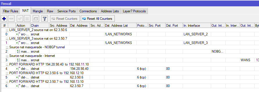
⚠️ Order is Critical: These specific src-nat mapping rules must be placed before the general masquerade rule added in the previous step. If they are placed after, the general masquerade will execute first, overriding these specific mappings.
/ip firewall nat
add action=src-nat chain=srcnat comment="LAN_SERVER_2 source nat on 62.3.50.6" dst-address-list=!LAN_NETWORKS in-interface=LAN_SERVER_2 to-addresses=62.3.50.6
add action=src-nat chain=srcnat comment="LAN_SERVER_3 source nat on 62.3.50.7" dst-address-list=!LAN_NETWORKS in-interface=LAN_SERVER_3 to-addresses=62.3.50.7
WARNING: rules order is important, here a screen of what it needs to look like.
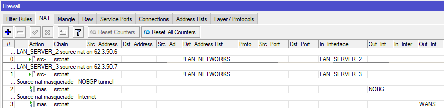
Mangle rules
The mangle rules section is where the routing magic happens. These rules are responsible for detecting which packets must be forced back through the NOBGP tunnel instead of using the native internet connection.
While the previous src-nat rules handle address translation, these mangle rules perform the essential routing mark that directs the translated packets onto the correct path.
⚠️ Rule Placement and Action are Critical: These mangle rules must be placed after your MSS clamping rule. Additionally, the action must include passthrough=no. Setting passthrough=no is crucial as it instructs the router to stop evaluating subsequent firewall rules for these marked packets, ensuring they are routed immediately and efficiently.
/ip firewall mangle
add action=mark-routing chain=prerouting comment="LAN_SERVER_1 via NOBGP if not local" dst-address-list=!LAN_NETWORKS in-interface=LAN_SERVER_1 new-routing-mark=NOBGP passthrough=no
add action=mark-routing chain=prerouting comment="LAN_SERVER_2 via NOBGP if not local" dst-address-list=!LAN_NETWORKS in-interface=LAN_SERVER_2 new-routing-mark=NOBGP passthrough=no
add action=mark-routing chain=prerouting comment="LAN_SERVER_3 via NOBGP if not local" dst-address-list=!LAN_NETWORKS in-interface=LAN_SERVER_3 new-routing-mark=NOBGP passthrough=no
Here a screenshot of how it look like at the end
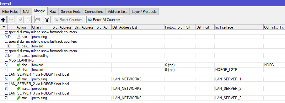
Port forwarding (dst-nat): utilizing your NOBGP public IPs
The primary interest of using NOBGP is precisely the ability to manage fixed public IP addresses for dedicated services. Below, we provide concrete examples showing how to implement port forwarding using your multiple NOBGP static public IPs.
On MikroTik RouterOS, the feature used for port forwarding is officially called Destination NAT (dst-nat).
/ip firewall nat
add action=dst-nat chain=dstnat comment="PORT FORWARD HTTP 194.28.98.40  to 192.168.11.10" dst-address=194.28.98.40 dst-port=80 protocol=tcp to-addresses=192.168.11.10
add action=dst-nat chain=dstnat comment="PORT FORWARD HTTP 62.3.50.6  to 192.168.12.10" dst-address=62.3.50.6 dst-port=80 protocol=tcp to-addresses=192.168.12.10
add action=dst-nat chain=dstnat comment="PORT FORWARD HTTP 62.3.50.7  to 192.168.13.10" dst-address=62.3.50.7 dst-port=80 protocol=tcp to-addresses=192.168.13.10
Firewall modification for NOBGP
WARNING: This rule have to be before the drop policy.
Allow packet to goes out via nobgp tunnel
/ip firewall filter
add action=accept chain=forward comment="Allow forward via nobgp internet" out-interface=NOBGP_L2TP
Internal management access
As the final step in the configuration, we need to add one last critical firewall rule.
This rule is designed to allow clients on your main LAN to reach all server VLANs for seamless administration and management purposes.
Flexibility Note: You can further refine this by constructing specific allow/deny rules to control traffic flow between the separate server VLANs, depending on your security requirements.
/ip firewall filter
add action=accept chain=forward comment="BRIDGE LAN to all servers vlans" in-interface=BRLAN
Few screenshots of the configuration GUI
Firewall
NAT
Mangle
Full router configuration
/interface bridge
add name=BRLAN

/interface ethernet
set [ find default-name=ether1 ] name=WAN_1
set [ find default-name=ether2 ] name=WAN_2

/interface pppoe-client
add add-default-route=yes default-route-distance=31 disabled=no interface=WAN_2 name=WAN_2_PPPOE password=PPPOE_PASSWORD user=PPPOE_USER

/interface VLAN
add interface=BRLAN name=LAN_SERVER_1 vlan-id=50
add interface=BRLAN name=LAN_SERVER_2 vlan-id=51
add interface=BRLAN name=LAN_SERVER_3 vlan-id=52

/interface list
add comment="List public interfaces" name=WANS
add comment="List private interface" name=LANS

/interface wireless security-profiles
set [ find default=yes ] supplicant-identity=MikroTik
add authentication-types=wpa2-psk mode=dynamic-keys name=SERVPERSO_WIFI supplicant-identity="" wpa2-pre-shared-key=WIFI_PASSWORD

/interface wireless
set [ find default-name=wlan1 ] frequency=auto mode=ap-bridge security-profile=SERVPERSO_WIFI ssid=SERVPERSO_LABO wps-mode=disabled
set [ find default-name=wlan2 ] band=5ghz-n/ac channel-width=20/40mhz-Ce disabled=no frequency=auto mode=ap-bridge security-profile=SERVPERSO_WIFI ssid=SERVPERSO_LABO wps-mode=disabled

/ip pool
add name=POOL_LAN ranges=192.168.10.100-192.168.10.149

/ip dhcp-server
add address-pool=POOL_LAN interface=BRLAN lease-time=8h name=DHCP_LAN

/interface l2tp-client
add connect-to=nobgp.servperso.net disabled=no name=NOBGP_L2TP password=NOBGP_PASSWORD profile=default user=NOBGP_LOGIN

/routing table
add disabled=no fib name=NOBGP

/interface bridge port
add bridge=BRLAN interface=ether3
add bridge=BRLAN interface=wlan2
add bridge=BRLAN interface=wlan1
add bridge=BRLAN interface=ether4
add bridge=BRLAN interface=ether5

/interface list member
add interface=WAN_1 list=WANS
add interface=WAN_2_PPPOE list=WANS
add interface=WAN_2 list=WANS
add interface=BRLAN list=LANS
add interface=LAN_SERVER_1 list=LANS
add interface=LAN_SERVER_2 list=LANS
add interface=LAN_SERVER_3 list=LANS

/ip address
add address=192.168.10.254/24 interface=BRLAN network=192.168.10.0
add address=192.168.11.254/24 interface=LAN_SERVER_1 network=192.168.11.0
add address=192.168.12.254/24 interface=LAN_SERVER_2 network=192.168.12.0
add address=192.168.13.254/24 interface=LAN_SERVER_3 network=192.168.13.0
add address=62.3.50.6 comment="ADD nobgp ip to loopback for NAT" interface=lo network=62.3.50.6
add address=62.3.50.7 comment="ADD nobgp to loopback for NAT" interface=lo network=62.3.50.7

/ip dhcp-client
add default-route-distance=30 default-route-tables=main interface=WAN_1

/ip dhcp-server network
add address=192.168.10.0/24 dns-server=192.168.10.254 gateway=192.168.10.254

/ip dns
set allow-remote-requests=yes

/ip firewall address-list
add address=192.168.0.0/16 list=LAN_NETWORKS

/ip firewall filter
add action=fasttrack-connection chain=forward comment="Established connexion fast track" connection-state=established,related hw-offload=yes in-interface=!NOBGP_L2TP out-interface=!NOBGP_L2TP
add action=accept chain=forward comment="BRIDGE LAN to all servers vlans" in-interface=BRLAN
add action=accept chain=forward comment="Allow port forward" connection-nat-state=dstnat
add action=accept chain=forward comment="Allow forward to public internet" out-interface-list=WANS
add action=accept chain=forward comment="Allow forward via nobgp internet" out-interface=NOBGP_L2TP
add action=accept chain=input comment="Allow estabished/related IN" connection-state=established,related
add action=accept chain=forward connection-state=established,related
add action=accept chain=input comment="Allow ICMP IN" protocol=icmp
add action=accept chain=forward protocol=icmp
add action=accept chain=input comment="Allow all input packet from non wan interface (lan)" in-interface-list=LANS
add action=drop chain=input comment="Default policy: drop everything else"
add action=drop chain=forward

/ip firewall mangle
add action=change-mss chain=forward comment="MSS CLAMPING" new-mss=1400 out-interface=NOBGP_L2TP protocol=tcp tcp-flags=syn tcp-mss=1401-65535
add action=change-mss chain=forward in-interface=NOBGP_L2TP new-mss=1400 protocol=tcp tcp-flags=syn tcp-mss=1401-65535
add action=mark-routing chain=prerouting comment="LAN_SERVER_1 via NOBGP if not local" dst-address-list=!LAN_NETWORKS in-interface=LAN_SERVER_1 new-routing-mark=NOBGP passthrough=no
add action=mark-routing chain=prerouting comment="LAN_SERVER_2 via NOBGP if not local" dst-address-list=!LAN_NETWORKS in-interface=LAN_SERVER_2 new-routing-mark=NOBGP passthrough=no
add action=mark-routing chain=prerouting comment="LAN_SERVER_3 via NOBGP if not local" dst-address-list=!LAN_NETWORKS in-interface=LAN_SERVER_3 new-routing-mark=NOBGP passthrough=no

/ip firewall nat
add action=src-nat chain=srcnat comment="LAN_SERVER_2 source nat on 62.3.50.6" dst-address-list=!LAN_NETWORKS in-interface=LAN_SERVER_2 to-addresses=62.3.50.6
add action=src-nat chain=srcnat comment="LAN_SERVER_3 source nat on 62.3.50.7" dst-address-list=!LAN_NETWORKS in-interface=LAN_SERVER_3 to-addresses=62.3.50.7
add action=masquerade chain=srcnat comment="Source nat masquerade - NOBGP tunnel" out-interface=NOBGP_L2TP
add action=masquerade chain=srcnat comment="Source nat masquerade - Internet" out-interface-list=WANS
add action=dst-nat chain=dstnat comment="PORT FORWARD HTTP 194.28.98.40  to 192.168.11.10" dst-address=194.28.98.40 dst-port=80 protocol=tcp to-addresses=192.168.11.10
add action=dst-nat chain=dstnat comment="PORT FORWARD HTTP 62.3.50.6  to 192.168.12.10" dst-address=62.3.50.6 dst-port=80 protocol=tcp to-addresses=192.168.12.10
add action=dst-nat chain=dstnat comment="PORT FORWARD HTTP 62.3.50.7  to 192.168.13.10" dst-address=62.3.50.7 dst-port=80 protocol=tcp to-addresses=192.168.13.10

/ip route
add disabled=no dst-address=0.0.0.0/0 gateway=NOBGP_L2TP routing-table=NOBGP suppress-hw-offload=no
NOBGP guides
- NOBGP – RouterOS 7: Dedicated public IP per server via DHCP and Far Gateway routing (No IP loss)
- NOBGP – ROS7 – One public ip per VLAN
- NOBGP – POP and supported protocols
- Mikrotik – RouterOS 6 – Full trafic via tunnel + ip pool
Bypass CGNAT & Dynamic IPs: NOBGP static Public IP is directly routed
Discover nobgp by servperso: Static public IPs and IP pools are routed directly to your network via a high-availability VPN tunnel.